An Arduino-controlled motorized panoramic tripod head
Juha Kaikko
Arduino-ohjattu moottoroitu kamerapää, kameranpyöritin tai kamerarobotti
Juha Kaikko
"I don't know anything about any of this, what is this thing?"
"En ymmärrä tästä mitään, selitä vähän?"
It is a device that can rotate a camera around so that it can take pictures at every direction while staying in exactly the same spot.
The photos can then be combined into one large image like so:
Tämä on laite joka voi pyörittää järjestelmäkameraa keskipisteen ympäri niin, että se voi ottaa kuvia joka suuntaan.
Kuvat voi sitten yhdistää yhdeksi isoksi panoraamakuvaksi:


"How does it work?"
"Miten se toimii?"
A bit of backstory:
I like photography, and I ran into these panorama images that were stitched from multiple shots.
I found a free software people were using for stitching (Hugin), as the normal photoshopping just won't do
since photos need to be stretched, rotated, cut and pasted correctly, taking lens properties into the account.
The software was amazing, in addition to normal rectilinear projection, it can create images with many different projections,
Including the stereographic projection.
If you take a shot to every direction covering the whole 360-degree field of view, including up and down, you can stitch the shots into one large image,
and with the stereographic projection you can then create these photospheres,
where you can look around into every direction.
You can also make those tiny planet
or inverse tiny-planet -images with the stereographic projection.
But there is a catch! Between each shot the camera must be rotated precisely around the lens's entrance pupil,
which is inside the the lens, to eliminate any parallax movement.
"Parallax is a displacement or difference in the apparent position of an object viewed along two different lines of sight" (Wikipedia).
So if the camera isn't rotated around the lens's entrance pupil in all three axis,
any objects that are at different distances from the camera seem to move in relation to each other, and then stitching produces bad results.
Sure, you can sometimes get 'ok' results with freehanding the camera,
you really need a tripod and panoramic head made for this purpose, but they tend to be expensive.
While researching the subject I stumbled upon a device that rotates the camera and takes the shots... And I really wanted one!
...Too bad it was around 1000€.
But then I bought a 3d printer and entered the wonderful world of Arduino and stepper motors
and this idea of designing and building my own motorized panoramic tripod head started to form.
Vähän taustaa:
Pidän valokuvauksesta, ja törmäsin internetissä näihin panoramakuviin jotka on yhdistetty useammasta kuvasta.
Löysin ilmaisen ohjelmiston (Hugin) jolla voi liittää kuvia yhteen paremmin kuin jollain perus-photarilla,
kun kuvia täytyy venyttää, kääntää, leikata ja liimata oikein, ottaen huomioon linssin ominaisuudet.
Hugin oli loistava tähän, ja tavallisen rectilineari projektion lisäksi sillä voi tehdä monia muitakin, esimerkiksi stereograafisia projektioita.
Jos ottaa kuvia jokaiseen mahdolliseen suuntaan kattaen koko alueen, myös ylös ja alas, voi niistä luoda tällaisia pallopanoramakuvia,
joissa voi katsoa joka suuntaan.
Sillä voi tehdä myös tällaisia pieniä planeettoja
tai käänteisiä pieniä planeettoja.
Mutta siinä on pieni juju: Kuvien välissä kameran tulee pyörähtää tarkalleen linssin sisällä olevan pisteen ympäri jossa valonsäteet leikkaavat, jotta ei tule parallaksiliikettä.
"Parallaksi tarkoittaa yleisesti sitä, että kun havaitsija liikkuu, niin paikallaan oleva esine näyttää liikkuvan taustaansa nähden." (Wikipedia).
Joten jollei kameraa pyöritä tarkalleen edellämainitun pisteen ympäri, kohteet eri etäisyyksillä näyttävät liikkuvan toisiinsa nähden, ja kuvien yhteenliittäminen tuottaa huonoja tuloksia.
Toki, joskus on mahdollista saada ihan "ok" tuloksia jopa vapaalta kädeltä, mutta oikeasti onnistuneisiin kuviin tarvitsee jalustan ja erityisen tähän tarkoitukseen tehdyn panoramapään.
Tätä asiaa tutkiskellessa törmäsin laitteeseen joka kääntää kameraa moottoreilla...
...Harmi vain ne maksoivat lähemmäs 1000 euroa.
Mutta niihin aikoihin hankin tee-se-itse 3d-tulostimen ja sitä rakentaessa ja käyttäessä alkoi muodostumaan idea omasta kameranpyörittimestä. Sen voisi rakentaa osin samoista osista.
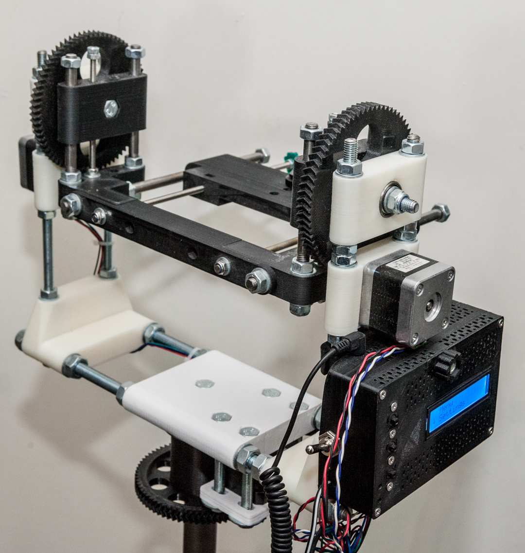
The design
My 3d-printer gave me an idea for the basic design, as some of it's frame is made out of 3d-printed parts and threaded rods.
The idea was to save in plastic while making the structure stronger, though it also ended up weighting more than I thought it would.
I wanted to use my Nikon D700 with the rotator, but as the camera body is really heavy (almost 1kg), it creates some challenges for the design.
And that's still without any lenses, too... And then I found out that the lenses I wanted to use, especially the 14mm wide-angle one,
have the entrance pupil quite far from the camera body, and it needs to be in the pivot point...
So the camera body needs to be sitting some 10cm (or more) from the pivot point, which creates a lot of torque.
Way more than any NEMA 17 stepper motors have.
Then I made some calculations, as I needed to know how much torque a 2kg mass would cause if it was about 10cm from the pivot point,
and how much holding torque a typical NEMA 17 stepper motor has. I can't remember the details but even two motors were not enough,
in fact I would need the two motors and 1:8 gears to transmit the power.
The material causes some limitations though as the printed plastic isn't excatly the strongest possible,
and the printer can't really make fine enough details with 0,4mm nozzle, so the gears need to be quite large.
Too small teeth could just snap or deform in use, as the torque will be pretty high.
Also, if I used a smaller nozzle, I sure could print finer details, but the parts would be even weaker.
This led to the decision to have the camera sit horizontally and to have the motors at the both ends.
Luckily the gears were not a problem as I knew I could print my own gears, as the extruder in my 3d-printer has printed gears.
The OpenScad file for gears is open source so I used it.
I could make the design more compact and move the motors below the whole system and use belts instead of direct gears.
There are many different sizes of timing belts in ebay and they would probably work really well, But for now I'll leave it as an upgrade path.
There were other parts that were more difficult to design, like the platform where the camera sits on,
as it needs to be able to move back and forth, but still be sturdy enough. Originally it was attached with 8mm threaded rods and fixed in place with nuts.
It was moveable but finetuning it was cumbersome, so I got some 8mm smooth rods so the platform can slide more easily,
and it's being held in place with 5mm threaded rods and nuts embedded in the platform, so when I rotate the rods, the nuts force the platform to move back or forth.
The height of the platform can be adjusted similarly, though it could be left fixed, at least as long as I use the same camera,
since the distance from the bottom of the camera body stays the same even if I change the lens.
Another maybe even more difficult part was the how the rotator is attached to a tripod, and I ended up with a solution where I turn the tripod's upper part(25mm pipe) upside down
and mount the rotator directly on it.
There is a small thrust bearing at the end of the hole in the pipe, and another larger bearing on top,
and the whole rotator sits on the large bearing,
and they are all fastened together with a bolt through the bearings and into the pipe (I had to remove the end cap from the pipe for this to work).
Even if the hole where the pipe goes in is quite tight fit, the whole rotator isn't as stable as I'd like, since the whole thing is so heavy.
Though running with lower speed and stopping for a moment before shooting removes all the vibrations.
The design
Tosiaan, 3d-tulostin antoi idean perusdesignistä, tulostettuja osia ja kierretankoa.
Tosin jotta rakenteesta sai tarpeeksi tukevan, osien täytyi olla kohtalaisen järeitä, eikä kierretankokaan varsinaisesti ole mitään kovin kevyttä.
Tästä seurasi että tästä prototyypistä tuli varsin painava.
Halusin pyörittimen pystyvän käyttämään Nikon D700 järjestelmäkameraani, mutta se on myös varsin painava.
Pelkkä runko painaa jo lähes kilon, ja pienimmät objektiivit alkavat jostain 350 grammasta.
Sitten huomasin että laajakulmaisessa 14mm obejektiivissa jota suunnittelin käyttäväni, valon leikkauspiste on todella lähellä objektiivin etupäätä,
joten kameran runko jää melko kauas pyörähdyksen keskipisteestä... Noin 10cm.
reilun kilon paino 10 sentin vääntövarren päässä luo niin paljon vääntöä että NEMA 17 -kokoisissa askelmoottoreissa ei mitenkään riitä vääntö.
Toisella objektiivilla paino tai etäisyys voisi olla vielä korkeampi.
Joten tein joitain laskelmia, otin kohdepainoksi 2kg ja 10cm vipuvarren, ja vertasin vääntövoimaa tyypilliseen NEMA 17 -askelmoottorin specseihin.
Kävi ilmi että tarvitsisin kaksi moottoria 1:8 välityksellä että vääntö riittää.
3-d -tulostetut rattaat oli selvä valinta välityksen hoitamiseen, etenkin kun rattaille löytyy valmiita generaattoreita OpenSCAD -ohjelmalle.
Materiaali, eli tulostettu muovi, tosin aiheuttaa joitain rajoituksia.
0,4mm tulostuskärjellä ei saa tarkinta mahdollista tulostusjälkeä, eikä se myöskään ole niin vahvaa kuin ruiskuvalutekniikalla tehty.
Tästä johtuen rattaiden täytyy olla melko suuria.
Designistä voisi tehdä kompaktimman, siirtämällä moottorit alas ja käyttää hihnoja rattaiden sijaan.
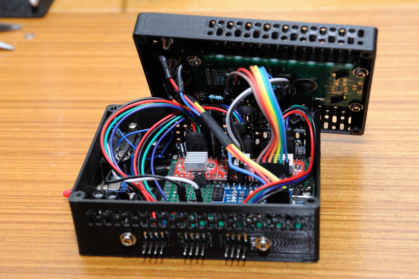
Arduino and other electronics
I needed something to control the stepper motors with,
and the obvious device for this is exactly the same that controls the stepper motors in the 3d-printer: Arduino.
Though board in the printer is the Arduino Mega, I wouldn't need as many connections as it has.
In fact the Arduino Nano was perfect, and even better, they can be bought as cheap as 2-3€ from Ebay.
Also the stepper motor drivers were around 1-2€ a piece in Ebay, a Pololu A4988 or it's clone. My 3d-printer has the same drivers.
So, I also got some small generic prototype boards from ebay,
soldered the arduino and the stepper drivers onto one and made the connections by soldering tiny wires on the backside.
I also needed to shoot the camera with the arduino, so I got some 5V relays and a shutter release cable for the camera.
But even if arduino outputs 5V from the logic pins, it's too weak to switch the relay so I used a small transistor to boost the power.
Then I designed and printed a box for the electronics. First I was going to add a small fan into the box, since the stepper drivers heat up quite a bit,
but I ended up just making a lot of small ventilation holes in the box desing. Later the main power switch broke because it couldn't handle the power.
The new bigger switch wouldn't fit, so I had to modify the box design and re-print it.
The Arduino nano uses 5V DC power, like what you get from USB connector, but it also has a 5V regulator built-in so it can accept up to 12V DC.
The stepper drivers work best with 12V DC, so the obvious power source is a 12V battery or a transformer.
The whole device uses around 1.3A when turned on, and the usage stays about same if it's staying still or moving,
since the stepper motors need to hold the position when they are not turning.
Arduino ja muu elektroniikka
Tarvitsin jotain jolla ohjata askelmoottoreita,
ja ilmeinen valinta tähän on tarkalleen sama laite jolla voi hallita 3d-printteriä: Arduino.
Tosin tässä ei aivan tarvita Arduino Mega:aa, vähemmätkin pinnit riittävät, kuten vaikka Arduino Nano, joita saa 2-3 eurolla Ebaystä.
Moottorinohjausyksiköt löytyvät myös Ebaystä noin 1-2 eurolla kappale, samaten prototyyppipiirilevyjä saa sieltä halvalla.
Kolvasin arduinon, moottorien ohjausyksiköt ja muut komponentit piirilevylle ja tein liitokset johdoilla takapuolelle.
Eihän se mikään kaunis ollut mutta toimi ensimmäisellä yrityksellä.
Arduinon täytyy myös pystyä laukaisemaan kamera, joten hankin 5V releitä ja laukaisukaapelin kameralle.
Lisäsin pienen transistorin boostaamaan arduinon pinneistä tulevaa virtaa jotta se jaksaa kytkeä 5V releen.
Suunnittelin ja tulostin myös rasian johon elektroniikat tulevat. Ensin meinasin lisätä rasiaan pienen tuulettimen, mutta päädyin vain tekemään siihen paljon reikiä ilmanvaihtoa varten.
Koko homma toimii 12V akulla tai muuntajalla, kun moottorinohjaimet toimivat parhaiten 12V jännitteellä, joka kelpaa myös arduinolle kun siinä on oma 5V regulaattorinsa.
The code
At the start of the project, Arduino (C/C++) was new to me, but I had a little experience with Java so getting started wasn't that difficult after all.
There is also a lot of example code for different devices usually used with an Arduino, which is very helpful.
Everything can be controlled with 3 buttons on the box, up, down and select.
The program I made has multiple operation modes, for example the 360x180 panorama,
and the panning timelapse mode.
The default settings are ok in broad daylight, but if you want to shoot with longer exposure time, it can be changed in the settings menu.
It also defaults to 14mm lens, but there are many other sizes to choose from, like the 50mm which produces much higher quality than the 14mm, but requires more shots.
Of course, when changing the lens, the distance from the pivot point needs to be calibrated again, too.
The 3d pieces are also made out of code, since in OpenSCAD everything is typed as code.
For example, you create a 10x10x10mm cube with cube([10,10,10]);
Moving and rotating the cube works like this: translate([0,0,10])rotate([45,0,0])cube([10,10,10]);
This moves the cube 10mm up in z-axis and rotates it 45 degrees in x-axis.
Of course you can replace the numbers with variables, too.
I wanted to move the project from Arduino to ESP8266, so I could control it from my cellphone over wifi.
The ESP8266 board can be programmed with Arduino IDE too and it can use mostly the same code.
I already got most of the things working when I was testing around, but when I tried to run stepper motors with it, it just crashed.
It turns out that because it has the wifi, the normal delays and other stuff cannot be used, since the wifi module crashes if there are too long delays.
And the whole stepper driver is full of delays. I'd have to make my own driver which wouldn't use delays... But it turned out to be difficult.
So for now that idea is on hold.
I've also been holding off on publishing any of the code because I use other people's libraries and I'm not sure how I should deal with it.
Koodi
Projektin alussa Arduino, C ja C++ eivät ennestään olleet kovin tuttuja, mutta olin vähän koodaillut Javalla joten alkuun pääsy ei ollutkaan kovin vaikeaa.
Arduinolle löytyy myös paljon esimerkkejä joka auttaa jonkin verran.
Laitetta voi ohjata kolmella kotelossa olevalla napilla: ylös, alas ja valinta.
Tekemässäni ohjelmassa on monta eri toimintamoodia, esimerkiksi 360x180 panorama,
ja pyörähdys-timelapse.
Oletusasetukset toimivat päivänvalossa, mutta esim pidempi valotus yökuvaukseen on valittavissa asetusvalikossa.
Oletuksena ohjelma käyttää 14mm objektiivia, mutta valittavissa on muitakin, kuten 50mm, jolla saa paljon laadukkaampia kuvia kuin 14mm:llä, mutta tämä tarvitsee enemmän kuvia.
Linssiä vaihtaessa täytyy myös kameran etäisyys pyörähdyksen keskipisteestä kalibroida uudelleen.
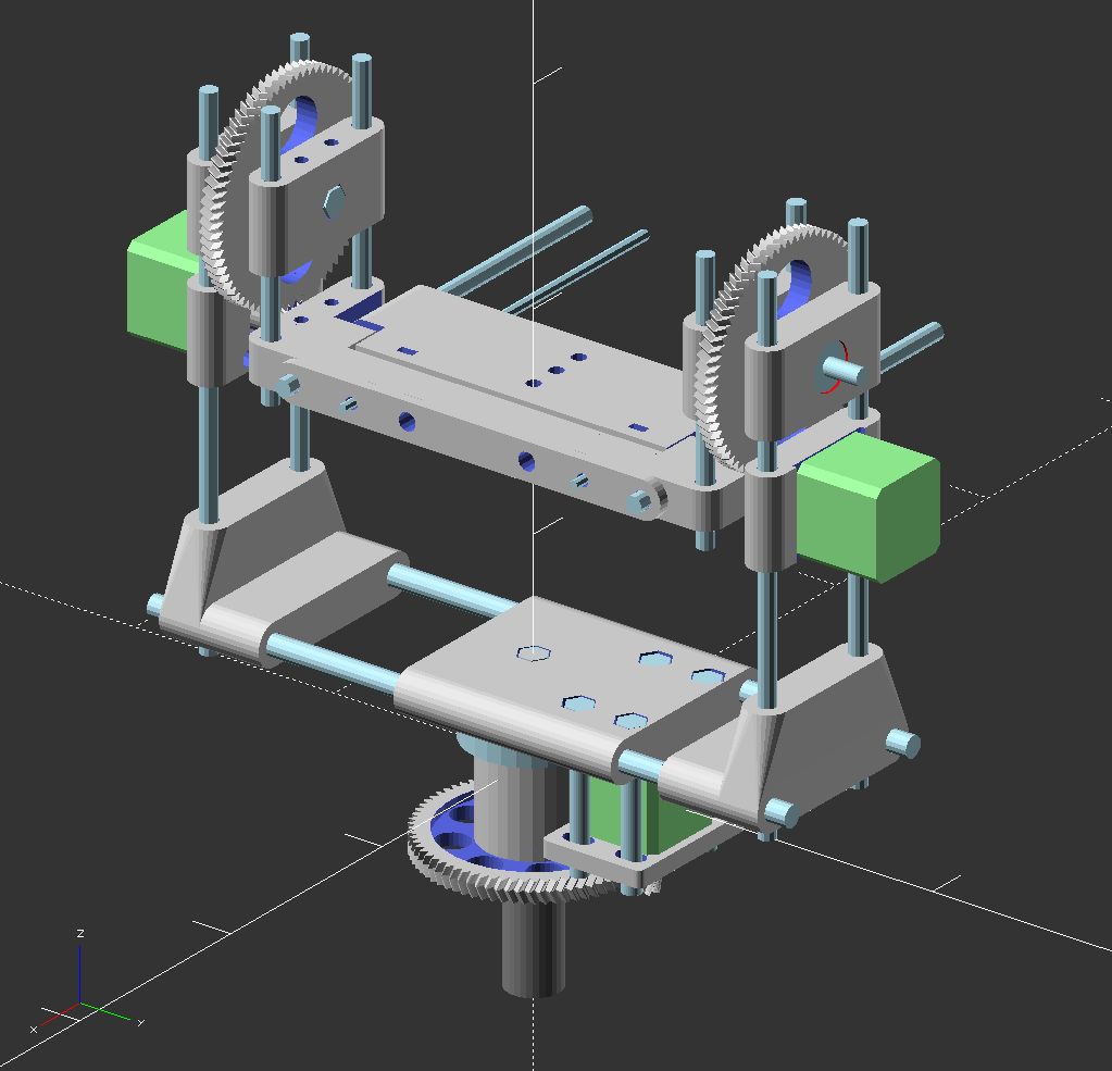
A 3d-view of the camera rotator.
Hmm, maybe I'll add some sort of part viewer? Or an animated version of how it operates? Maybe in the future?
The control box is missing from this, it's on a separate file.
3d-näkymä kameranpyörittimestä.